
产品展示/Products
Your location:home > products > GAS REGULATOR > 140 SERIES PRESSURE REGULATORS
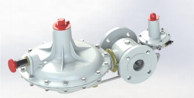
140 SERIES PRESSURE REGULATORS
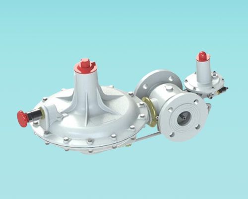
140 SERIES PRESSURE REGULATORS
- Product Name:140 SERIES PRESSURE REGULATORS
- Products:GAS REGULATOR > 140 SERIES PRESSURE REGULATORS
BALANCED VALVE
|
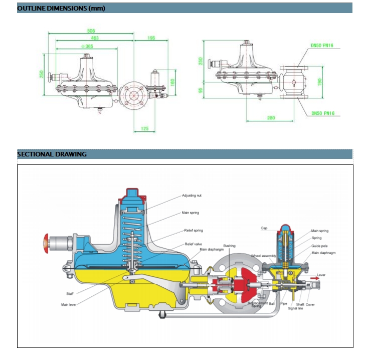
CONSTRUCTION FEATURES
|
particular, they have been constructed for maximum ease of maintenance: access to the valve seat and to the seals for inspection or replacement can be gained without removing the regulator from the line. The regulators come both in standard and high-pressure (AP) models:
140and 140-AP - with the addition of an outlet pressure relief valve
All models in the series are fitted with DN50 PN16 flanged connections.
|
OPERATION
|
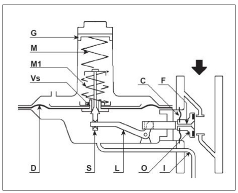
The movements of diaphragm (D) are relayed via stem (S) and lever (L) to valve disc (O). The outlet pressure acts on diaphragm (D) via impulse connection (I), generating a force that is countered by spring (M). The pressure exerted by the gas on the diaphragm works to close the valve while the pressure of the spring works to open it. Under steady gas flow conditions, the balance thus achieved between the two contrasting actions, ensures positioning of the valve disc so as to guarantee constant pressure outlet-gas flow. Any capacity variation causing a relative increase or
decrease in pre-set pressure activates the moving parts of the valve until a new balance is achieved, thus restoring desired pressure. The valve disc is kept in perfect balance by diaphragm(C), activated by the inlet pressure of the gas delivered via orifice (F). In this way, outlet pressure is kept constant and not affected by any variation of inlet
pressure. In regulators fitted with internal relief valve, stem (S) and diaphragm (D) are held together by spring (M1). When regulator is closed, any increase in outlet pressure over and above spring (M1) set-point causes diaphragm (D) to move upwards, thus opening the internal relief valve (Vs) itself, which releases small quantities of excess gas into the atmosphere. In regulators fitted with slam-shut valve, any pressure variation over and above valve set-point
trips the valve, thus shutting off gas flow.
|
SETTING
|
Turn the register (G) clockwise to increase outlet pressure and anticlockwise in order to decrease it. Next, check
pressure value by using either a master gauge with appropriate scale or a water column. With relief valve (Vs) fitted regulators, adjustment of triggering pressure is effected by means of the spring (M1) adjusting nut. Regulators are fully factory tested and set at the values shown on the data plate, which correspond to those specified in client
order.
|
COMMISSIONING
|
Proceed as follows:
Slightly open the outlet shut-off valve, and then slightly and very slowly open the inlet shut-off valve. Next, reset the slam-shut valve (when fitted) and wait for outlet pressure to stabilize, then fully and very slowly open the outlet
valve.
|
PERIODICAL CHECKS
|
It is recommended that the regulator be periodically checked in order to ensure its proper functioning.
1. Checking regulator
Slowly close the outlet shut-off valve and check pressure in the length of pipe between the regulator and the valve. If the system is functioning properly, an increase in outlet pressure will be noticed due to lock-up
pressure, after which pressure will stabilize. If, on the contrary, outlet pressure continues increasing, the
system is not functioning properly due to improper valve disc tightness. In this case, close the valve located upstream of regulator and carry out maintenance procedures as set out in general maintenance below.
2. Checking relief valve (when fitted)
Close the valve located downstream of regulator. Next, connect a manual pump or other similar device to a previously fitted impulse connection between the regulator and the valve and raise the pressure until relief valve is activated, i.e. until gas is released from vent.
|
GENERAL MAINTENACE
|
1. Warning
Maintenance should be carried out only by qualified, skilled personnel. If required, please contact our Technical Department or authorized dealers .
Before carrying out maintenance procedures, make sure that no gas under pressure is trapped in the regulator body. In order to release all gas from the regulator, first close inlet and outlet valves and then release gas from the line by opening the appropriate vent tap.
When carrying out general maintenance, replace all rubber parts. For this purpose, use only the spare parts included in LILI’S spare parts kit.
Maintenance operations do not require removal of valve body from the line.
2. General Maintenance
A. Remove screws (52) and clamp (53) in order to take off diaphragm case. By removing diaphragm case, the balancing unit and pad (22) will also come off.
B. Unscrew pad retainer (30) and check for proper condition of pad unit (22).
C. Loosen stem (19) and disassemble all balancing unit components. Carefully clean all parts with petrol. Check diaphragm (21) and replace any parts which are found to be worn out.
D. By means of the appropriate tool, unscrew seat (28) and check O-ring (23). Replace seat if worn or damaged.
E. Remove cap (1), ring nut (2) and spring (3), taking care to mark the exact position of the ring nut for remounting.
F. Remove screws (40) and take off cover (4) .
G. Remove the diaphragm assembly from the diaphragm case.
H. Strip the diaphragm assembly down into its various components. In the models fitted with relief valve,
unscrew register nut (5) and then remove spring (8), taking care to mark the height of the preloaded spring in order to reassemble it in its original position, thus ensuring proper setting of the relief valve. Finally, unscrew ring nut (11). For all other models, simply remove nut (5) and unscrew ring nut (11).
I. Check diaphragm (16), seal (39), relief valve (13) and O-ring (48). Replace any parts which are found to be worn or damaged.
L. Check O-rings (18 and 27).
3. Reassembling
Reassemble parts by carrying out the steps outlined in part 2 above in reverse order. Upon reassembling, make sure that each part moves freely. Moreover, take care that:
A. Take care of all the seals . Use utmost care to ensure against any damage during reassembling.
B. Diaphragm (16) is properly reassembled by lubricating it with some grease and by carefully fitting it into the case (34) .
C. All screws are duly tightened in order to ensure proper sealing.
D. There are no leaks, by using soapy water.
Copyright© 1995 - 2009 Egypt.com Inc. All rights reserved